Science and technology
working with nature- civil and hydraulic engineering to aspects of real world problems in water and at the waterfront - within coastal environments
![]() In an earlier piece, Civil Engineering on our Seashore, I have presented and broadly outlined the Coastal Engineering Envelope where several civil engineering measures were shown – that cater to the needs for protecting and developing the seashore. A brief of some 24 different kinds of coastal and port hydraulic structures were listed there. On this piece let us attempt to learn about the Storm Surge Barrier – but in a wider context of Flood Barrier Systems. The barriers as a way of managing water and floods – have two basic engineering components. The first is the dike on low lands, connected to the second component – the gated stream/river/estuary/waterway closure structures. The works represent a system that accounts for many engineering challenges – hydraulic, structural, geotechnical, and risk assessment – as well as impacts on the ambient environment defined by local Fluid, Solid and Life systems (see e.g. Environmental Controls and Functions of a River). In the back drop of Warming Climate with consequent Sea Level Rise, flood barrier systems are becoming increasingly relevant – as one of the management Strategies to cope with the threatening rising sea, and increasingly frequent and intense storm surge. This piece is built upon materials gleaned from several sources and websites. Unless specified otherwise, they include the following. On river floods: Hydraulic Design of Flood Control Channels, USACE EM 1110-2-1601; Hydrologic Frequency Analysis, USACE EM 1110-2-1415; and Design and Construction of Levees, USACE EM 1110-2-1913. On coastal flood/storm surge: Storm Surge Analysis and Design Water Level Determinations, USACE EM 1110-2-1412; Hurricane and Storm Damage Risk Reduction System Design Guidelines, USACE; and TUDelft (VSSD) Breakwater and Closure Dams (2008, 2nd ed). . . . 1. Flood Barrier Systems and Issues Before jumping on to discussing the flood barrier systems – perhaps it would be instructive to begin by introducing the Water Barrier concept in a broader context. Because all barriers under this generic term, and in the capacities of a hydraulic structure – have one common purpose – that is to protect an area from the onslaught of water actions. These protections can simply be sorted out against the actions of:
Wave and Current Forces, Agitations, Erosions and Scours: (1) emergent and submerged fixed breakwater; (2) floating breakwater; (3) sill, reef or weir catered to gradually weaken water forces; (4) beach nourishment; (5) a buffer zone of hardy and water tolerant plantations to reduce forces; (6) groin; (7) jetty and training wall to deflect forces; and (8) seawall, bulkhead and revetment; and (8) stone ripraps on banks and beds. Inundation and Runup by Propagating Flood Waves: (1) on banks or shorelines – stone ripraps, earthen dike or monolithic vertical flood wall with channel closures and sluice outlets; (2) purposely built sand dune; (3) isolating an area to create polders by ring, or partial-enclosure dikes or flood walls with channel closures and sluice outlets; (4) gated barrier on streams, rivers, estuaries and river mouths – designed for actuation in times of unwanted high waters caused by flood waves of all sorts – tide, storm surge and tsunami; (5) managing channel networks through diversion barrages, closure dams and dikes; (6) the crucial step of implementing closure dams; and (7) pumping stations to augment drainage relief of the protected area. Sedimentation Management: (1) sluice outlet to drain out water and accumulated sediments, together with gates to prevent entry of sediment-laden high-stage water into the protected area; (2) sediment trap dug into channels to be dredged occasionally; (3) updrift to downdrift sediment by-pass to balance accretion-erosion; (4) updrift breakwater to trap sand, and prevent channel sedimentation by breaking the continuity of littoral drift; and (5) occasional dredging of silted basins and channels. Effects Assessment: It is customary that all modern engineering measures must accompany an assessment of their effects on the Fluid, Solid and Life Systems – with clear identifications of impacted areas on the surrounding – both in short and longterm perspectives. But, many engineering measures failed to take proper account of effects and remedies. The 2012 USGS report (C1375): A Brief History and Summary of the Effects of River Engineering and Dams on the Mississippi River System and Delta – outlined in vivid terms some effects of river engineering and protection works – that totally changed the character and regime of a river – adversely affecting its living dynamic equilibrium process of sustenance. Many such works have been (perhaps even being) installed around the world – without due diligence of assessing their effects and impacts – thus weighing their pros-and-cons on the interdependent Fluid-Solid-Life systems. Risk Assessment: Flood barrier systems are a costly investment tasked to protect areas, properties and lives against extreme hydraulic events and forces that have the overwhelming power of destruction. Therefore it is a compelling necessity to complete a risk assessment procedure with due diligence and earnest. The 2012 NAP publication #13393 – Dam and Levee Safety and Community Resilience: A Vision for Future Practice – discusses some of the Flood Barrier safety and risk mitigation issues, and community involvements. Risks and safety standards are usually described by coining different acronyms. New acronyms appear as emphasis shifts or as new thinking emerges. They result from the underlying realization that risk is not something that can be eliminated – but rather can be minimized. As discussed in the Uncertainty and Risk Article – risk quantification is a product of the uncertainty associated with the forcing functions – and both the short and long-term consequences or damaging actions of that force. It requires addressing a question – how to define a certain Safe Tolerable Threshold (STT) during the minimization processes. In the context of the collapse of Flood Barrier Systems – the STT definition and risk characterization mean finding an acceptable damage threshold that would ensure safety of lives and properties. When defining standards in one way or another – the aim is to arrive at risk as low as possible – or safety is as high as possible. Both the approaches are definable in probability scales. As can be understood, the rationality of finding a satisfactory cost-benefit ratio underlines all STT definitions. But, then there is no uniquely acceptable definition across the board – therefore disputes, court-cases and legal definitions and re-definitions come into the picture. Aspects of this are also shared in an ASCE Collaborate Discussion. With this brief layout of water barriers, let us move on to discussing the specific issues of flood barriers. Among the many measures identified above, the ones belonging to the group described in 2 are the focus of this piece. Let me first briefly elaborate some key hydraulic basics of this group – then move on to outline some major Storm Surge Barriers – with detailing out some aspects of the Venice MOSE project (image credit: anon). . . . 2. Flood Barrier Hydraulics It is necessary to comprehend some key hydraulic technical issues – that are important in aspects of planning, designing, construction, and functions. In all these aspects, different methods and practices are implemented in ways – how a barrier handles the potential and kinetic energies – in eliminating, reducing or modulating their power. Let us attempt to see them. In barriers installed to prevent flooding due to inundation and runup – potential energy is gradually elevated as the hydraulic head difference increases between the two sides of a barrier. One knows too well that the forces caused by the difference – exerted on an earthen dike, a vertical monolithic wall, or a gated barrier structure – are what cause failures (see Civil Engineering on our Seashore). The threats to their stability and integrity take different dimensions and can be translated into: The first hydraulic issue that comes to one’s mind – is the selection of an upper-envelope extreme event up to which a given barrier system can be designed to withstand and provide protection. Methods and issues related to defining such an event have been discussed in two pieces posted earlier – Uncertainty and Risk; and The World of Numbers and Chances. Among the two modes for flooding, inundation is like the gradual encroachment by a carpet of water with concentration of currents when the dispersing flood-wave faces resistance. In contrast to this, broken-wave runups are forceful in actions with impacts on structures and bed. A standing pressure force develops on the water retaining side of the structure. This pressure representing potential energy causes very high kinetic energy when released (e.g. a 1 m of head difference could generate a flow velocity as high as 4.5 m/s). There are also some dynamic elements to the pressure field – induced by propagating disturbances and/or by surface waves. These forces apply an overturning moment on a vertical wall, and cause pore pressure on an earthen dike. Earthen dikes are designed to minimize the effects of pore water pressure. At a certain moment when the freeboard is less than some tolerable limits, the potentials of overtopping and eventual failure emerge – in particular in the regions of weaknesses. In such cases, the power of concentrated flows continues to erode and topple the barrier until the forces diminish, and the hydraulic head difference between the two sides is levelled off. A vertical wall causes some reflections of the dynamic pressure and surface waves. A sloped earthen dike, on the other hand is dissipative by nature. Areas enclosed by dikes require a drainage sluice outlet gated structure. Most often a flap gate proves to be a very cost-effective alternative. It is a simple structure with gates hinged at the top while the bottom part can flap outward – to let the draining out of accumulated water from inside the protected area. The gates are designed not to flap inward to prevent entry of water from outside. To cope with adverse drainage-gradients (that often happen at very high tide, but most notably during storm tide when receiving basin water level is higher than the protected area), pumping stations are installed at the drainage outlet structure to pump out accumulated water from inside the protected area. . . . 2.1 Closure Dams In many flood barrier engineering – a closure dam is required to close the original channel to let the flow divert toward the newly-installed gated-structure. For a uni-directional flow, closing of the original river course is easily done after diversion. For tidal channels, an intensive sequence of activities is required to close the final water-gap. This is mostly accomplished during a short window of neap-tidal slack water. Purposely-built middle islands – together with well-mobilized equipment and workforce are employed to close the gap at one go. While the closing operations continue, the peripheral parts of the dam are protected simultaneously by dumping rocks. I had the opportunity to learn about different aspects of closure dam hydraulic engineering while studying at Delft – working on a group thesis on Asan Bay closure dam in Korea. Also, had the opportunity to be present and witness the labor-intensive works of Feni River Closure Dam in Bangladesh. More on closure dams are available at: TU-Delft 2008, Breakwaters and Closure Dams, 2nd edition; CIRIA Rock Manual 2006, Design of Closure Works (Ch 7). In my 1993 paper {Practices, Possibilities and Impacts of Land Reclamation Activities in the Coastal Areas of Bangladesh. In: Grifman PM and Fawcett JA (Eds), International Perspectives on Coastal Ocean Space Utilization, University of Southern California Sea Grant Publication, pp. 343-356} traditional practices of building large-scale cross-dams or closure dams in Bangladesh were discussed. The 1956-57 Cross-dam 1 and the 1964 Cross-dam 2 – were implemented to close some dying branches of the Meghna Estuary, and some 52,000 ha of land was reclaimed. . . . 2.2 Other Hydraulic Aspects An important step in flood barrier engineering is to design and construct measures for preventing scour of channel bed. A bed scour is initiated and intensified, because installation of gate-housing structures reduces the channel cross-sectional area – thus increasing the flow velocity, and inducing scour-causing vortices around the gate structures (see Turbulence, and Wave Structure Interactions & Scour). Based on many years of experience, Dutch engineers developed methods and special equipment to place woven straw mattresses on the channel bed. Ballasted by rocks, the mattress acts as a filter to prevent escaping of bed sediments – as well as becomes the prepared foundation on which structures can be placed. This is unique, in a sense that many other methods rely on founding the gate-structure deep into the solid bed on which superstructures are built upon. Engineering of gates on barrier openings have many familiar forms: e.g. gates sliding against structure piers vertically; swing gates hinged to the bottom; swing gates hinged to the bank; rotating drum gates; inflatable gates; gates sliding horizontally; swing flap gates hinged to the top; etc. Some key considerations that lead to the choice of one or the other are: convenience of recess structure for housing the gates when not in operation; strength of the gates and power required to operate them to withstand the design high hydraulic heads, etc. A very important effect of implementing storm surge barriers – is the reduction of tidal prism (see Managing Coastal Inlets). This happens because of the reduced cross-sectional area. Since the behavior of the Fluid (in this case Water) System is changed – the ambient characteristics of the Solid and Life Systems – dependent on water properties and circulation are affected. Therefore a thorough environmental effects assessment is imperative. . . . 3. Highlights of Some Major Storm Surge Barriers In the world of modern flood barrier engineering, the first one to occupy the history book is the 32 km long Afsluitdijk closure dam in the Netherlands completed in 1932. This dam separates the shallow IJsselmeer Lake from Wadden Sea. The primary purpose of this dam was to reclaim land from the lake. Starting from this great feat of hydraulic engineering, let me highlight some major storm surge barriers completed around the world.
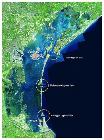
 Delta Works, the Netherlands: These works refer to massive barriers, navigation locks and dikes – constructed to control and prevent storm surges entering through several branching delta estuaries of the Rhine-Meuse-Scheldt river system. The works were commissioned after the devastating storm surge flooding of 1953. The last one of the Delta Works was finished in 2010 together with environmental restoration works. The gates on the openings of the barriers vary in technical innovations from sliding to bank-hinged to inflatables. The only sea arm that remains open in the Netherlands is the Western Scheldt that leads to the Antwerp Maritime Port in Belgium. With the threat of rising sea, strengthening of existing structures is on the plan. Thames Barrier, London, England: The same 1953 North Sea storm surge that prompted Delta Works in the Netherlands – was also the reason for initiating the Thames Barrier. Commissioned in 1984, the purpose of the barrier system comprising of the dikes – was to protect low lands of the greater London area from the North Sea high tide and storm surge propagating through Thames Estuary. It was built on the 520 m wide estuary by dividing it in 4 basic segments and 2 navigational spans. The barrier structure openings are equipped with rotating steel drum gates that rest on the channel bed when sleeping, and are rotated to rise in the event of unacceptable forecasts of high tide or storm surge. IHNC Storm Surge Barrier, USA: This barrier (Inner Harbor Navigation Canal) was constructed by US Army Corps of Engineers near New Orleans on the confluence of Gulf Intracoastal Waterway and Mississippi River Gulf Outlet in 2013. The purpose of the barrier was to protect some of the low lying vulnerable areas of greater New Orleans against storm surges from the Gulf of Mexico and Lake Borgne. The barrier system consists of flood walls, bypasses, navigation locks and gated barriers. To reduce the risk of flooding in the greater New Orleans area - a massive $14 billion project - the Hurricane and Storm Damage Risk Reduction System (HSDRRS) is being built by USACE with supports from local and outside consultants. The system is scheduled to be completed in 2023. A recent discussion throws further light on the New Orleans Barrier system. Saint Petersburg Dam Complex, Russia: The Saint Petersburg Flood Prevention Facility Complex is a 25 km barrier system – completed in 2011 to protect Saint Petersburg against storm surge coming from the Gulf of Finland. Saint Petersburg is founded on low marshy lands located in Neva Bay – and has seen the onslaught of some 340 devastating floods in the past. The system also forms part of the dike ring road that passes through the gated barrier structure as underwater roadway tunnels. It includes some 30 water purification units designed to maintain the water of Neva Bay healthy. Among many others in the planning process – a massive storm surge barrier (New York Harbor Storm Surge Barrier) is planned to protect the Lower New York Bay from the onslaught of storm surge coming from the Atlantic through the Outer Harbor. . . . 3.1 MOSE Project Venice, Italy Let me begin with a little bit history. Venice marshy islands started to get settled by refugees when they fled from barbarian attacks in the 5th century CE. It gradually became important and powerful as a maritime port and harbor. Venice lagoon gradually silted up by sediments brought in by 3 rivers. At sometime later, the river outfalls were diverted away from the lagoon to prevent sedimentation. In the 20th century, many wells were dug in Venice to extract water for agriculture and industry use. The extraction induced more subsidence of the marshy lands – and was banned only in the 1960s. Present subsidence rate of Venice is about 1 – 2 mm/year. Long waves such as tide, storm surge and tsunami are subjected to transformation as they propagate from open water to constricted areas (see Transformation of Waves) – in the process waves are amplified and distorted. Similar process happens, as the low Mediterranean tide gets amplified as it enters Adriatic Sea to Venice. As an example, in January 2020, a 30 cm tide at Catania, Sicily amplifies to 100 cm at Malamocco, Venice. A term known locally as acqua alta is used to refer to tidal flooding of the Venice city center – tide reaching to + 0.8 above local datum. The analyses of 1872 – 2006 tide records show that acqua alta mostly occurs in the months from October to December due to both astronomical and meteorological phenomena. Since about 1950s, the frequency and intensity of acqua alta have been registering high, due to subsidence as well as the rising sea level of the Adriatic. When tide is + 140 cm, about 90% of Venice is flooded. Low level flooding during high tide are becoming more common – presumably due to rising sea and subsidence. In the backdrop of all these, the MOSE (Modulo Sperimentale Elettromeccanico) flood barrier project was conceived in 2001 and construction began in 2003. It consists of 78 independently moving closure gate elements at 3 inlets (18 at Chioggia; 19 at Malamocco; 20 at Lido-Treporti and 21 at Lido-S. Nicolo). These 3 inlets are located on the barrier island chain that separates Venice Lagoon from the head of Adriatic Sea. The purpose of the project is unique – in a sense that unlike many other major storm surge barrier projects around the world – it is planned to operate rather regularly to lessen the effects of high tides and storm surges penetrating into the Venice lagoon. The rectangular gate elements were designed to rest on seabed recess structure when not active. The resting is ensured by filling the elements with water. Activation of the elements is initiated when the tide is forecasted to reach +110 cm. The elements are raised from their recesses by pumping compressed air into the elements to drain out water. The anticipated completion timeline of the project is 2022. Among the 3 inlets, the Malamocco Inlet is designed to accommodate marine traffic to the Venice Port during the inlet closures. Differences of opinion appeared about the adverse effects of closures – in terms of harming ecology, of very high cost, and of doubts about the effectiveness of the inlet structures. Additionally, concerns were expressed about navigational delays and the cost for such delays on transportation. A recent discussion indicates the high frequency of rising seas and how the barrier system is equipped to cope with that. . . . It has been a great pleasure writing this piece. Let me finish it with a little Koan: Why let it wither away, some water-of-life on the plant would have worked to let it stand upright and unfold the fragrance of flower. . . . . . - by Dr. Dilip K. Barua, 26 January 2020
1 Comment
|
Dr. Dilip K Barua
Archives
October 2024
Categories |